

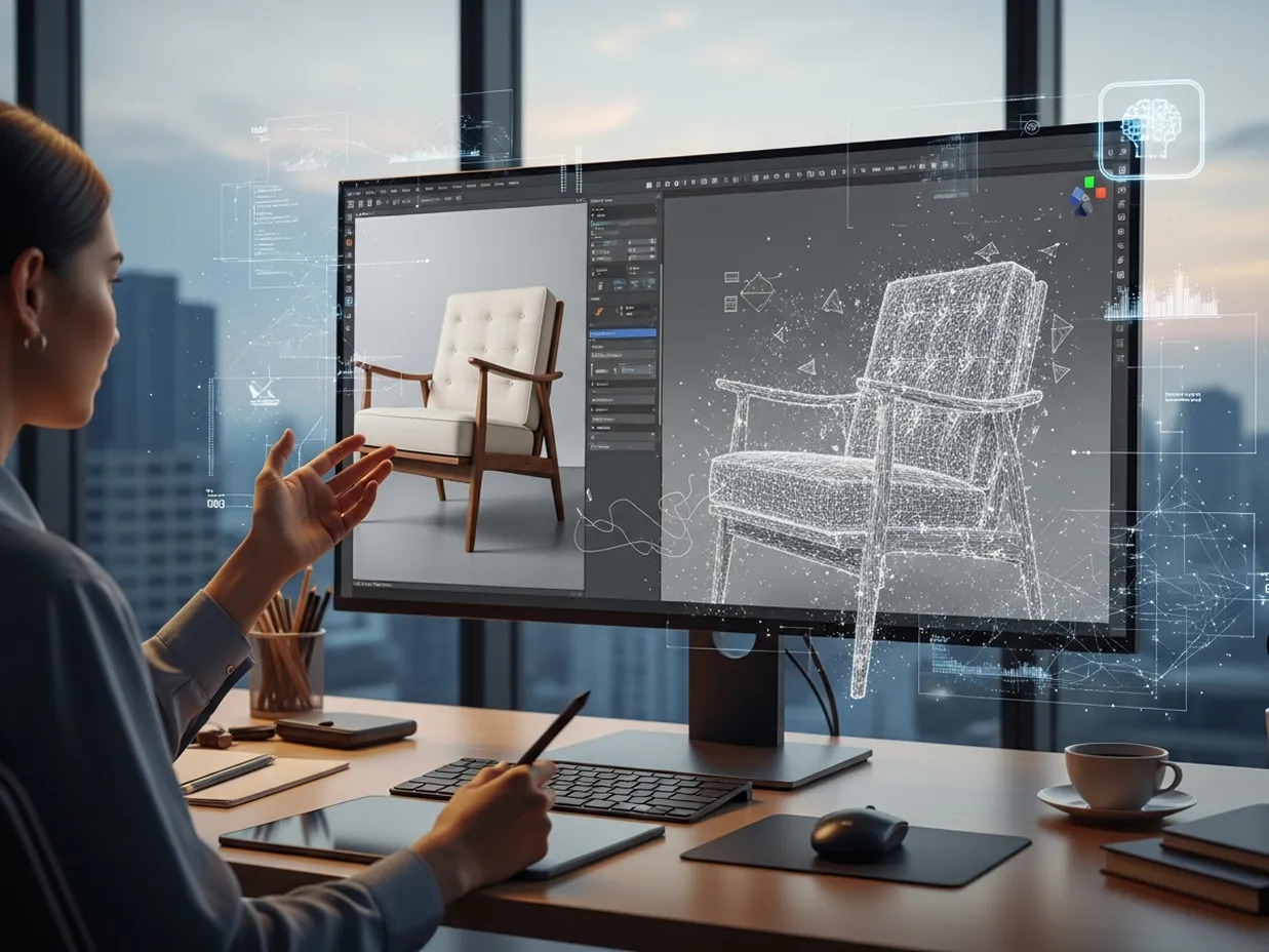
AI can now turn a written description, sketch, or product image into a 3D result within minutes. Yet the term “3D model” covers several very different outputs. Some systems make attractive concept images. Others produce polygon meshes for visualization or 3D printing. A smaller group creates editable CAD geometry. Whether a result works for CNC machining, molding, or batch production depends less on generation speed and more on its geometry, dimensions, tolerances, material assumptions, and design-for-manufacturing review.
What Does AI Generate from Text and Images?
Text-to-3D and image-to-3D systems usually start by reading shape, style, proportion, and surface details. A prompt such as “compact aluminum enclosure with rounded corners and front ventilation” may create a recognizable form. It does not automatically set exact wall thickness, hole positions, fits, threads, or assembly clearances.
The first common output is a rendered concept or multi-view image. This helps with styling discussions but holds no true 3D engineering geometry. The second is a polygon mesh, usually exported as STL, OBJ, FBX, or GLB. Meshes suit visualization, games, and many additive-manufacturing tasks. They remain hard to edit by dimension. The third is a solid or surface CAD model, often exchanged through STEP or a native CAD format. This type fits engineering work better, although it still needs validation.
How Do Current AI Industrial Design Approaches Compare?
Different platforms solve different parts of the design process. A fair comparison should focus on the type of output and the work still required after generation.
| Platform | Core Approach | Best Suited For | Main Limitation |
| Meshy | Text or image to textured polygon mesh | Concept exploration, presentation assets, and some 3D-printing workflows | Mesh output is generally less suitable for precision machining without remodeling |
| Zoo Design Studio | Conversational CAD that creates editable geometry from prompts | Dimension-driven mechanical concepts and prompt-based CAD creation | Prompt quality, geometric inspection, and engineering review remain important |
| Autodesk Fusion | Constraint-based generative design connected with simulation and CAM | Exploring alternatives based on loads, materials, and manufacturing methods | Requires structured engineering inputs rather than only a short visual prompt |
| nTop | Implicit modeling, simulation, and computational design | Lattices, complex structures, and performance-driven components | Steeper learning curve than simple text-to-3D tools |
| Momaking | An AI industrial design workflow combining text or image input with concept development, structural modeling, and downstream DFM or prototyping support | Teams seeking a more integrated handoff from early concept to engineering support | Exported geometry, dimensions, and process assumptions still require engineering checks |
No single tool fits every project. Mesh generators focus on speed and appearance. Conversational CAD tools focus on editable geometry. Engineering platforms focus on constraints, simulation, and manufacturing integration.
What Makes a 3D Model Manufacturing-Ready?
A manufacturing-ready model must describe more than the outer shape. For CNC machining, the geometry should normally be a clean, watertight solid or a well-defined surface model that CAM software can import. Critical dimensions, datums, tolerances, tool access, corner radii, and stock conditions must be set.
For injection molding, engineers must think about draft angles along with uniform wall thickness. They also review ribs, bosses, and parting lines. Undercut analysis helps spot issues early. A suitable material rounds out the needs. For sheet metal, bend radii and bend allowances play a big role. Hole-to-edge distances require care too. Flat-pattern behavior needs checking as well. For 3D printing, mesh integrity keeps models solid. Minimum feature size sets clear limits. Orientation changes the print results. Supports often become necessary during the build. Post-processing wraps up the steps.
A STEP file is therefore not proof that a model is production-ready. STEP can carry accurate CAD geometry. It may still contain impractical features, missing tolerances, or geometry that cannot be produced economically by the selected process.
A Practical AI-to-Manufacturing Workflow
A reliable workflow starts with AI for concept generation, not automatic production approval. First, define the product’s function, target dimensions, material, manufacturing process, and non-negotiable interfaces. Next, generate several concepts and select one based on function as well as appearance.
Then inspect the output type. A mesh may need to be rebuilt as parametric CAD, while an editable solid may only need refinement. Add critical dimensions, assembly features, tolerances, and material data. Run geometry checks, simulation where necessary, and process-specific DFM analysis. Finally, create a prototype and compare the physical result with the design intent before releasing production data.
This staged approach keeps the speed of AI while keeping engineering decisions traceable.
What Are the Main Limitations?
AI-generated geometry can contain hidden defects, unsupported assumptions, asymmetry, weak connections, or unrealistic internal structures. Image-based systems may also guess dimensions that were never visible in the reference. Complex assemblies, moving mechanisms, safety-critical parts, and regulated products still require qualified engineering review.
Data security and intellectual-property terms should also be checked before uploading confidential drawings. Teams should understand whether inputs are stored, used for model training, or available to other users.
FAQ
Q: Can AI Replace Traditional CAD?
A: AI is more likely to change how CAD work begins than to eliminate CAD. It helps cut the time spent facing a blank page. It also offers different options and handles routine modeling tasks on its own. Traditional CAD stays vital for exact dimensions, design history, assemblies, drawings, tolerances, and controlled revisions.
Q: Can an AI-Generated STL Be CNC Machined?
A: Sometimes, but it is rarely the preferred starting point. STL contains triangles rather than precise analytic surfaces. A machinist may be able to use it for limited operations. Rebuilding or converting the part into clean CAD geometry usually provides better control.
Q: Which Tool Should a Designer Choose?
A: Choose according to the required output. Use mesh-generation tools for visualization and rapid form studies. Use conversational CAD for prompt-driven editable parts. Use engineering platforms for simulation, optimization, and manufacturing integration. The final decision should rest on test exports, editability, accuracy, security, and compatibility with the existing CAD/CAM workflow.